Thursday, October 27, 2011

Relays (CIRC11)

Purpose
The purpose of this circuit is to explore the role of a relay.


Equipment
  • 1 x Transistor
  • 1 x Relay
  • 1 x Diode
  • 1 x 560 Ohm Resistor
  • 1 x 2.2K Resistor
  • 2 x LEDs
  • 14 x Wires
  • 1 x Arduino Uno
  • 1 x Breadboard & reference sheet
Program Details

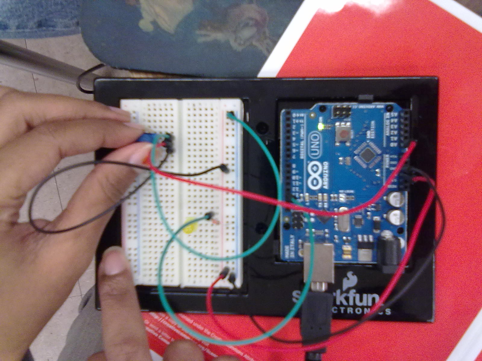
     Assembling this circuit takes up to around 7 minutes. There are a lot of important pieces besides the wires that need to be placed correctly. Some of these pieces have been used before, however it is still important to know how each piece functions to understand the circuit. The diode allows one way current flow, and the transistor either switches or amplifies current. This function is similar to the relay which acts as a switch for even large amounts of current. Since we're working with a lot of current the resistors are stronger as well. Below & beside are pictures of assembled circuits. 


     The code for the following circuit is as straightforward as blinking. In fact it follows the same format except instead of turning the LED on and off directly. We send the message to the pin connected to the relay. The LEDs are connected to the relay as well, so we're using one pin to control the bulk of the outputs. 

Results
     
     The LEDs worked fine, as instructed by the program. It did seem some what underwhelming, however I can imagine that it more LEDs were added it'd be pretty significant. This would be a good next step.

Tips

     The only important tip with this circuit is to connect the relay properly. If one of its 3 pins aren't connected properly, it won't function. Also make sure the wire that connects the relay to the Arduino board is connected to pin 2 on the Arduino board. 

Next Steps & Associated Modifications

     A simple addition would be to connect more LEDs to the circuit (specifically to the relay). This way we can see how useful the relay really is. The program code for this stays the same. However this circuit isn't simply limited to LEDs, try a motor! Or even the piezo element! The code that can be applied to basically all these outputs is explained below.


int ledPin=2; //the relay is connected to pin 2

void setup()
{ pinMode (ledPin, OUTPUT); } //make it so the relay sends output to LED

void loop()
{
  digitalWrite (ledPin, HIGH); //turns LED on via relay
  delay (1000); //wait a second
  digitalWrite (ledPin, LOW); //turns LED off via relay
  delay (1000); //wait a second before repeating this blinking effect
  
}

References:

1. Spark Fun Inventor's Starter Guide
2. http://www.oomlout.com/a/products/ardx/circ-11 

Wednesday, October 26, 2011

The Piezo Element (CIRC-06)

Purpose
     This circuit investigates how to operate a piezo element (creates sound) using the analog system and pulse frequency.


Equipment

  • 1 x Piezo Element
  • 4 x Wires
  • 1 x Breadboard & breadboard sheet
  • 1 x Arduino Uno
Program Details

     This circuit is probably one of the most easily assembled circuits, yet very effective. Assembly takes about 2-4 minutes. Simply attach the wires to the appropriate pins, and make sure one of them (9) is analog. This gives output signals to the piezo element, whose pin is connected parallel to the pin 9 wire on the breadboard. The assembled circuit looks like this.


     The program for this circuit uses various functions to play the note. First we introduce the number of notes, the notes, beats and temp. Then each note is given a frequency. The program then combines all the variables with the appropriate operators (multiplication and division), to play the note for the designated amount of time. The main function, which plays the tune is a repeating loop at the end of the code, after setting everything up. More detail is in the comments in the last section of this report.

Results


     Music to my ears! After watching LEDs for all this time, finally we can hear something different. The programming associated to this circuit plays a simple melody, however by adding your own notes, you can play any tune! Definitely trying this one later.


Tips


     Assembly is not hard to follow. Simply be careful with your programming, make sure the numerical values correspond. Also, make sure you understand the program format before initializing it.


Next Steps & Associated Program Modifications


     There are several tricks you can play on with this program. This includes changing the tempo (int tempo=#), tuning the notes by adjusting their individual frequencies as desired, and changing the melody!! I think that last one is fun, so below is the code for playing Happy Birthday.


int speakerPin = 9; //the piezo element is connected to this digital pin


int length = 13; // the number of notes in this tune+1
char notes[] = "ccdcfeccdcgf "; // the notes in this tune, where each note 
//corresponds to a specific frequency
int beats[] = { 1, 1, 1, 1, 1, 2, 1, 1, 1, 1, 1, 2, 4 }; //the beat, or length of
//each note introduced above
int tempo = 300; //the tempo for the tune


void playTone(int tone, int duration) 
{
  for (long i = 0; i < duration * 1000L; i += tone * 2) //sets up how long the tone is played
  {
    digitalWrite(speakerPin, HIGH);//turns the piezo on
    delayMicroseconds(tone); //for the length of the tone
    digitalWrite(speakerPin, LOW);//then the piezo is turned off
    delayMicroseconds(tone); //delayed for length of tone
  }
}


void playNote(char note, int duration) 
{
  char names[] = { 'c', 'd','f', 'e', 'g', 'f' }; //the different notes for the tune
  int tones[] = { 1915, 1700, 1432, 1519, 1275,}; 
  //their corresponding tone calculated by: 1/(2*notefrequency) 
  
  for (int i = 0; i < 6; i++)
  {
    if (names[i] == note)
    {
      playTone(tones[i], duration); //plays the note and tones introduced just above
    }
  }
}


void setup() 
{
  pinMode(speakerPin, OUTPUT); //setting pin 9 as output
}


void loop() 
{
  for (int i = 0; i < length; i++) 
  {
    if (notes[i] == ' ') //this section plays all the notes introduced earlier in
    //the array notes[], until all notes (12), the # less than variable 'length' is played
    {
      delay(beats[i] * tempo); // after the 'for' section there is a rest before repeating
    } 
    else 
    {
      playNote(notes[i], beats[i] * tempo); 
    }
    
    delay(tempo / 2); 
  }
}


Reference: Spark Fun Inventor's Guide

Temperature (CIRC-10)

Purpose
The purpose of this lab is to analyze how a temperature sensor works. Here we are reporting information instead of controlling something.


Equipment

  • 1 x Temperature Sensor (TMP36)
  • 5 x Wires
  • 1 x Breadboard & reference sheet
  • 1 x Arduino Uno
Program Details

     Assembling this circuit takes up to 5 minutes, usually less. It is important to wire the temperature sensor correctly, it is often overlooked. See the assembled circuit below.


     The program starts by introducing the only variable component attached to a pin, the temperature sensor. In the setup the program establishes a 'serial' connection with the computer so that later we can print the results. There is a button beside upload, a box with an antenna which opens the screen to display the output. The number in the brackets is the transmitting speed.  Since this program looks at a different overall function, displaying output on the computer, the program is a little different, but not necessarily hard. The main loop starts by branching off into the function 'getVoltage'. This function reads the temperature, converts it to a readable code and then returns the value. This value, 'temperature' is then converted to an actual temperature reading. Finally, 'Serial.println(temperature0' displays the temperature.

Results

      Due to the malfunction of our temperature sensor, the outputs that were printed on the screen were unreliable. The temperature was constantly fluctuating from numbers as low as -40, to numbers as high as 300, and then numbers close to 0. We tried another sensor, but none of them worked properly (same problem).Afraid of the sensor catching on fire, we were advised to detach the temperature sensor. Below is a screen shot of the outputs we were getting:


Tips

     The most important precaution is not to touch the temperature sensor with your hands, while and right after it is unplugged. This is because there is a risk of malfunction, you can burn yourself and the sensor can even catch on fire. As soon as you notice that the temperatures are drastically incorrect, unplug the Arduino from the computer. Also while assembling, make sure the temperature sensor is pugged in correctly before uploading the program.

Next Steps & Associated Program Modifications

     The output of this program is so basic, there are only small possible modifications. For example, the serial speed at the beginning can be changed. We can also display the temperature in another way, farenheit! This can be done by simply changing the line that calculates the temperature. See the code below.


int temperaturePin = 0; //the temperature sensor is connected to analog pin 0


void setup()
{
  Serial.begin(9600);  //in the setup we are starting a connection with the computer in order
  //to later print the information
}


void loop()                    
{
float temperature = getVoltage(temperaturePin);  //gets the digital reading from the temperature
                                                  //sensor by running the function getVoltage (see bottom)
temperature = (((temperature – .5) * 100)*1.8) +32;          //converts the digital number to the appropriate
                                                  //temperature in farenheit
Serial.println(temperature);                     //prints the temperature
delay(1000);                                     //pause for a second before repeating
}


float getVoltage(int pin)
{
return (analogRead(pin) * .004882814); //gets the appropriate temperature reading (analog),
                                        //converts it to a number in the digital range,
                                        //and returns it to float(temperature)
}


Reference: Spark Fun Inventor's Guide

Monday, October 24, 2011

Lets Fight (Arduino Robotics)!

This website is perfect to by equipment for robotics and other Arduino parts.
Below is a screenshot.


     I believe this website is perfect to buy all the necessary equipment for a robotics unit, if it were to run. It has a wide range of products, specific to robotics. You can buy a whole robotics kit (Ex: Humanoid), specific robotic parts for your own creation, and even other Arduino products. The robotic kits, for instance the Humanoid features kits by the brand of Bioloid. The problem is these are very costly, it can cause over a thousand dollars! This is not a problem because individual parts such as: wheels, hubs, casters, DC motors & controllers, acutators, hobby servos, lights, displays and pretty much any robotic element you can think of, is sold seperately. You can choose your own dimensions, brand, etc., for your own creation. The section specific for Arduino provides a wide range of equipment for starters, and creators, which is not specifically robotic. An example of these cool parts include a serial LCD display, or a buzzer (only $5). Finally, the bottom of the left menu allows you to shop for equipment based on the manufacturer, for those who have their favourites. On the top menu, the section 'Community', includes helpful forums on robotics, and cool pictures on advanced projects. I think it's definitely worth checking out to develop robotic skills.                                                                                                                   

Sunday, October 23, 2011

Welcome To Arduino

This website gives a good introduction to Arduino, answers FAQ, has hardware details, an Arduino Tutorial  and even some cool projects.

Screenshot: 


     I believe this a good introductory website because it gives a beginner user, a hardware overview to the circuit board (see Arduino FAQs on left menu). Even someone who upgraded their Arduino may find this website useful because it compares the new Arduino Uno to the older versions. In a way, the FAQ section gives the history, or evolution of the Arduino circuit board. Furthermore, the vocabulary used in this section can be applied to any programming technology, which broadens our knowledge even more. The side menu also has links to forums with helpful administrative support, advanced arduino projects, and tips for educators! I think this is great because now anyone can start teaching Arduino, or learning Arduino themselves using this website. If you want to buy the parts, the website also has a link to a reliable website (adafruit) that sells all the parts necessary to fulfill your various Arduino needs. 


     The top menu can lead you to a helpful Arduino Tutorial (to follow: Learn > Arduino Tutorial), complete with 6 lessons, a 'Help' section, and more details on additional compoenents such as: LCDs, Ethernets, etc. Lesson 0 introduces the essential pieces for this tutorial, complete with pictures and helpful details. For instance, telling the positive end of an LED from a negative. Lesson 0 also consists of software installation instructions for all Windows, Mac and Unix. Lesson 1 is somewhat of a followup which ensures that everything is fully functional, and gives you a brief description of the basics. This lesson even discusses possible errors and solutions to them so that the program runs smoothly in the future. Further lessons run you through the experiment and have follow up exercises. I believe this is an excellent tool t o make sure students understand every aspect of what they just learnt. Furthermore, whenever a new piece is brought in to the picture to use, the website recaps all the necessary equipment. The 'HELP!' section is useful because it addresses some annoying syntax errors you may run into. Again, there is a link to a website that sells the equipment. The projects (to follow: Projects > Arduino > ....) may seem advanced however if people are earnest it is complete with the necessary equipment and instructions. Definitely worth the time if you're interested.


*The website is by a university graduate named 'Limor' (go to Home>Pwr for more information). 

Photo-Resistor (CIRC-09)

Purpose
The purpose of this circuit is to explore the function and application of a photo resistor.

Equipment
  • 1 x Photo Resistor
  • 1 x LED
  • 1 x 330 Ohm Resistor
  • 1 x 10k Ohm Resistor
  • 6 x Wires
  • 1 x Breadboard & Reference Sheet
  • 1 x Arduino Uno
Program Details

     The photo resistor is yet another type of resistor, except this time sensitive to light (photons).   For this reason, in real life applications, the input value from this resistor can be fairly accurate. Another advantage is that the photo resistor doesn't require us, humans, to manipulate it. It is sensitive to the environment. When the setting is dark, there will be high resistance and no output, vice versa. The code for this program illustrates this more clearly. 

     However first, the circuit needs to be assembled, which takes 5-9 minutes. Follow the breadboard and attach the photo resistor properly. See the assembled circuit below.


     The code for this program doesn't integrate analog and digital signals, it is purely analog. The photo resistor is the input, and the LED is the output. First, the photo resistor assigns a value to 'lightlevel'. This value is then adjusted so that it ranges from 0-255. The 'analogwrite' function can then take this value and use it to change the state of the LED accordingly.

Results

     First we assumed that the photo resistor functioned the other way, so as to illuminate dark areas, so we thought we wired it wrong. However upon reading the guide and program, we understood it well. The circuit functions as it should, dimming and brightening according to the resistor. Another new aspect in the program we learnt was the ability to adjust the scale, and check over. This is the first time we've seen the program use a 'check for errors' mechanism with Arduino.

Tips

     The only major tip would be to wire the resistor properly for the circuit to function, key aspect. The photo resistor is also a fragile and sensitive piece, so handle with care. With the programming, make sure the numerical values are accurate with the ranges. If the range is too big, the 'analogwrite' function will not work.

Next Steps & Associated Program Modifications

    Again, small modifications to the program can change the results to lead to a different output. For instance, we can recreate what our group thought should happen with this circuit, dark room is illuminated, by simply altering the last line. See below.


int lightPin=0; //photo resistor is connected to analog pin 0. 
int ledPin=9; //LED is connected to pin 9 (PWM)

void setup()
{ pinMode(ledPin, OUTPUT); } //the LED is output

void loop()
{
  int lightLevel = analogRead(lightPin); //assign the input from the photo resistor to this 
  //new varuable
  lightLevel = map(lightLevel, 0, 900, 0, 255); //scale the input to 0-255 instead of 0-900
  lightLevel = constrain(lightLevel, 0, 255); //makes sure the scale is correct
  analogWrite(ledPin, 255-lightLevel); //subtract the value from 255 and send it as output
  //so that the LED functions opposite from the conventional way
}

Another easy modification is using the threshold method to create a switch. This follows the same principles as 'THE SWITCH' in the previous circuit. 


Reference: Spark Fun Inventor's Guide

Potentiometers (CIRC-08)

Purpose
The purpose of this circuit is to investigate the purpose of the potentiometer (variable resistor).


Equipment

  • 1x Yellow LED
  • 1 x Potentiometer
  • 1 x 330Ohm Resistor
  • 6 x Wires
  • 1 x Arduino Uno
  • 1 x Breadboard & reference sheet
Program Details

     Assembling this circuit is fairly easy, take around 4-7 minutes. It is most important to place the potentiometer correctly because it controls the LED in this program. The potentiometer takes analog signals to turn the LED on and off digitally. Therefore the wiring is a key player in this circuit as well. See the assembled circuit below. 


      Similar to the past lab, the program for this circuit starts by introducing the input pin (for potentiometer), output pin (LED) and a variable, in this case 'sensorValue', which receives the input values. In the loop, the program starts by reading the analog value (input) from the sensor, and storing it in the variable. The LED is then turned on, and delayed by the value of sensorValue (input value), and then turned off and subsequently delayed by the sensorValue before reading the potentiometer again. Note that the LED is actually blinking really fast (milliseconds) to produce the assigned output. The resistance corresponds to time since the analog reading translates to time in the digital reading. 


Results


     After analyzing the program and uploading it to the circuit. We played with the potentiometer, and it was nice to see the output understanding how the analog reading (sensory) translated to a digital output. This resistor seems way cooler than the small 2 pin ones. If you think about it, there are also many applications of this, such as audio control, dimming lights, television control, etc. 


Tips


     Make sure you attach the wires to the Arduino Uno without confusing the analog and digital pins, because the communication of these as input and output is integral to this circuit. Also make sure the three pins of the potentiometer are placed correctly in order for it to function. The programming, again is pretty straight forward, just make sure you know the key concept, translation of analog reading to digital, before you program the circuit.


Next Steps & Associated Program Modifications


     There are many simple modifications that can utilize the potentiometer for different purposes. This includes fading (dimming lights) and creating a switch. I think both of these are unique modifications, so below I have the code and explanations for both.


//THE SWITCH
//The assigned threshold acts as a switch


int sensorPin=0; //input pin, poteniometer
int ledPin=13;// LED pin


void setup()
{
  pinMode(ledPin,OUTPUT); //sets LED as output
}


void loop()
{
  int threshold=512; //value of the variable 'threshold', also analog
  if (analogRead(sensorPin)>threshold) //if the input from the potentiometer (sensorPin)
 // is greater than the value of threshold...
  {digitalwrite(ledPin, HIGH);} //turn the LED on
  else 
  {digitalwrite(ledPin, LOW);} //or else, when sensorPin<512, turn the LED off
  
}


/*FADING
*All of the program uses analog components. The LED is assigned the value from the *potentiometer, translated to the appropriate number of bits.
*/


int sensorPin=0; //input pin, poteniometer
int ledPin=13;// LED pin

void setup()
{
  pinMode(ledPin,OUTPUT); //sets LED as output
}


void loop()
{
  int value=analogRead (sensorPin) /4; //reads the potentiometer and divides the value by
  //4 so that it could be used by the 'analogWrite' function in the next step. This value
  //is stored in the variable 'value'
  analogWrite (ledPin, value); //the LED's state is on full power, off, or somewhere in 
  //between, depending on 'value'
  
}


Reference: Spark Fun Inventor's Guide


Pushbuttons (CIRC-07)

Purpose


To control a circuit, here specifically LEDs, using pushbuttons. Here, the user gets to control the circuit personally with touch. 


Equipment

  • 1 x red LED
  • 2 x pushbuttons
  • 1 x 220Ohm Resistor
  • 2 x 10kOhm Resistor
  • 7 x Wires
  • 1 x Breadboard & reference sheet
  • 1 x Arduino Uno 
Program Details

     This experiment is especially cool because we are controlling the circuit with our own hands, we determine the output, LED on or off. This is why the coding is simply a matter of reading our signals. Although there are two buttons attached, only one is of use right now. However, refer to 'Next Steps & Associated Program Modifications' to utilize the other button. Assembling this circuit took around 5-10 minutes. It is simply a matter of carefully following the attachments, so as to minimize any sources of error. See the assembled circuit below.

Assembled circuit

     The code for this is all straightforward. The only new concept is using a variable to read the pushbutton and control the state of the LED. First, the code declares the inputs, outputs, and variable 'val', which reads the state. The repetitive part 'loop()', the main function, uses the function 'digitalread' to read the state of the button, input. If the input value is high, unpressed, the LED is turned off. In any other time (else) the input value is low, pressed, the LED is turned on. 


Results


     First we did not notice that the second button didn't do anything, so we were worried. Soon after, we looked at the guide and realized all was good. This experiment worked as the program suggested. It wasn't as exciting as it sounded, but it was cool to learn how our own movements translate into electrical input/outputs. 


Tips


     The biggest tip would be to assemble the resistors and pushbuttons carefully, and look over the circuit before uploading the program. Since there are wires passing overhead, make sure the pushbuttons, especially close to the breadboard, is placed correctly the first time.


Next Steps & Associated Program Modifications


     Now, to utilize the second button, simply make one button turn the LED on, and the other turn the LED off. This means there will be 2 inputs. See the modified program below, as directed by the kit.


//start by introducing the pins. Order below: LED, button 1, button 2


int ledPin=13;
int inputPin1=3;
int inputPin2=2;


void setup() 
{
  pinMode(ledPin,OUTPUT); //the LED is now output
  pinMode(inputPin1, INPUT); //the first button is now input
  pinMode(inputPin2, INPUT); //the second button=input
}


void loop()
{
  if(digitalRead(inputPin1) == LOW) //if button 1 is pressed
  {
    digitalwrite (ledPin, LOW); //turn the LED off
  }
  else if (digitalRead(inputPin2)==LOW) //OR if button 2 is pressed
  {
    digitalwrite (ledPin, HIGH); //turn the LED on
  }
}


Reference: Spark Fun Inventor's Guide

Saturday, October 22, 2011

8 Outputs (CIRC-05)

Purpose

     The purpose of this investigation is to utilize the 'shit register' and create 8 outputs.

Equipment
  • 8 x Red LEDs
  • 8 x 330 Ohm Resistors
  • 1 x Shift Register
  • 19 x Wires
  • 1 x Breadboard 
  • 1 x Breadboard sheet
  • 1 x Arduino Uno
Program Details

     The breadboard sheet for this circuit is probably the most intimidating one, however it is simply a matter of strategy and patience. You must take your time. See the Tips section. This circuit utilizes wiring, LEDs and resistors from the past circuit. The shift register is simply a matter of aligning it in the right hole. After assembling our circuit and checking over the resistors numerous times, we programmed.

     The program is understandable once you understand the concept behind the shift register. This shift register recieves data of what to do from each of the 8 pins, in binary language, then outputs it to the LED. Only certain LEDs turn on, creating a blinking pattern. First the variables, and delay times are set. Then the program starts repeating the function of turning on certain lights. The number i, determines which LEDs turn on as it is sent to the 'updateLEDs()' function. The value of i, is assigned in binary to the shift register, and that determines which LED turns on. In confidence we uploaded this program and watched as only two LEDs turned on. We checked the wires and resistors, another group did as well. Until finally we realized the LEDs were the problem. We overlooked placing the LEDs in correct orientation. The +/- pins of the LED were placed into the breadboard randomly. After fixing this, our circuit worked fine. The LEDs seemed to blink in a random fashion, but after looking at the program closely, we realized the program was following a set of 255 combos in binary that is sent to the shift register. Unfortunately, there was not enough time to obtain a picture of the working circuit. However, here are pictures of the assembled, partially working circuits. 


Results

     The results are not that exciting in proportion to all the assembly, however the phenomenon behind it is quite astonishing. The one shift register provides the ability to control 8 outputs, using 255 different combinations! Note, the pattern is not random, it corresponds to the value of i, in binary, which spans 8 bits. If everything is simply wired the right way, the 8 LEDs should turn on and off as instructed.


Tips

     The ultimate advice with this circuit is to take your time, because with this many equipment, it is too easy to plug something wrong, miss something, etc. First count out the correct number of pieces. Then attach them to the breadboard one by one. For instance, all the wires, then all the LEDs, etc. The advised order is the shift register first, because it is lowest to the breadboard, then LEDs because it'd be a hassle attaching it under all that wire, then the wires. And finally the resistors, because they border everything else. Also make sure one pair of hands tends to the breadboard at a time, it is less confusing and much more efficient that way.

Next Steps & Associated Program Modifications


     Another way to control these pins is to turn them on one after another, then off one after another, similar to CIRC-02. In this code, the 'loop()', is replaced with the 'repeat function', where i counts to 8, using the 'changeLED(i,state)' function to turn the LEDs 'ON' then 'OFF'. See below.


int data=2; 
int clock=3;
int latch=4;
//the pins above are associated to the shift register


void setup()
{     //the introduced pins will be used as outputs
  pinMode (data, OUTPUT);
  pinMode (clock, OUTPUT);
  pinMode (latch, OUTPUT);
}


void loop()
{
  changeLED(int led, int state); //repeatedly run this function
}


void changeLED(int led, int state) //function which turns the LEDs on and off
{
  int delayTime=100;//delay time between each time function is repeated 
  for (int i=0; i<8; i++)//pins 0-7, so this is repeated until i is less than 8
  //which is 7
  {
    changeLED (i,1); //turns the appropriate LED on, similar to HIGH
    delay(delayTime); //delayed by 100ms before repeating
  }
  for (int i=0; i<8; i++)//for pins 0-7
  {
    changeLED (i,0); //turns the LED off, similar to LOW
    delay(delayTime); //delayed by 100ms before repeating
  }
  
}


References


1.  http://oomlout.com/a/products/ardx/circ-05/
2. Spark Fun Inventor's Guide