The purpose of this circuit is to investigate the purpose of the potentiometer (variable resistor).
Equipment
- 1x Yellow LED
- 1 x Potentiometer
- 1 x 330Ohm Resistor
- 6 x Wires
- 1 x Arduino Uno
- 1 x Breadboard & reference sheet
Program Details
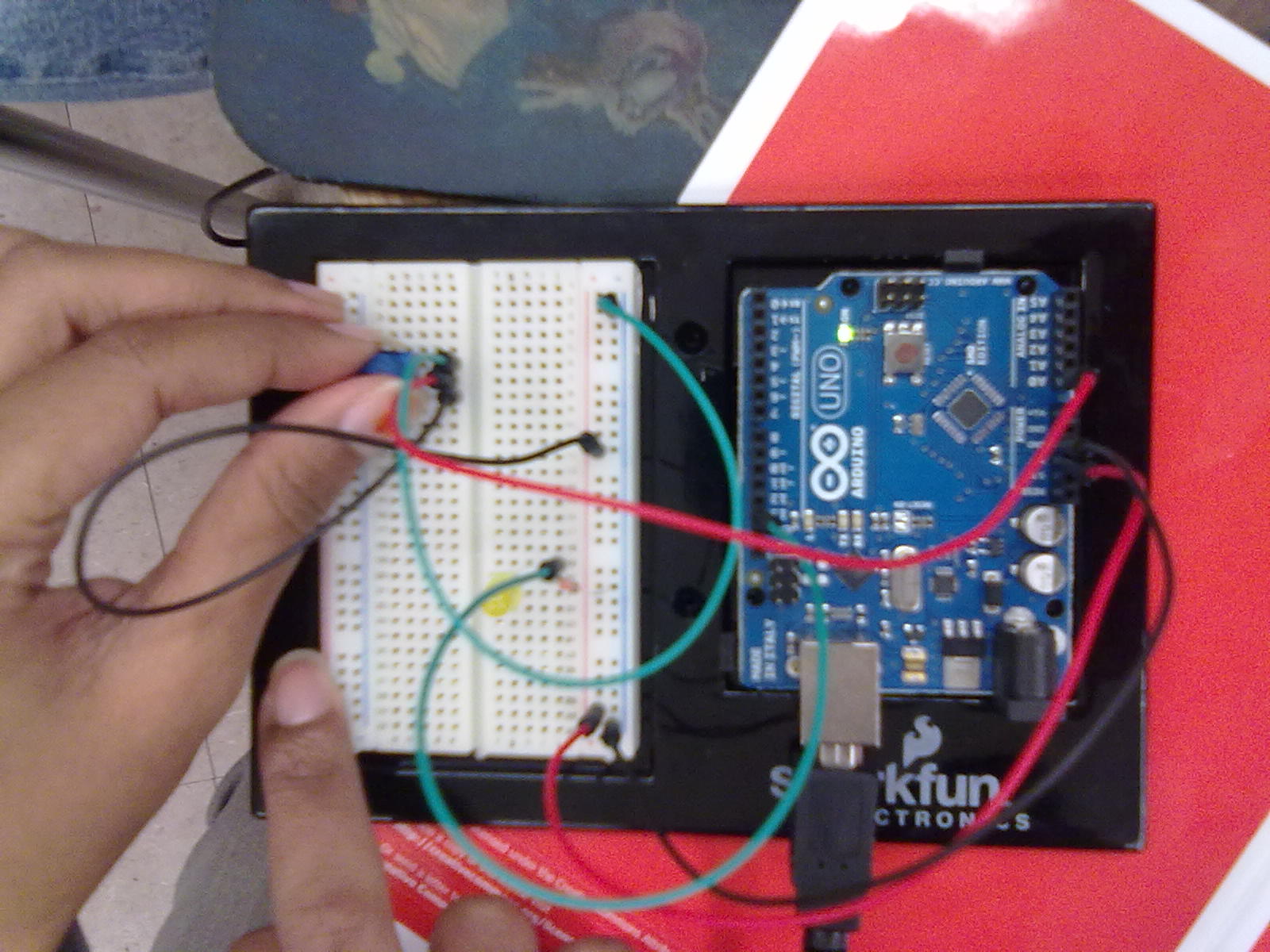
Assembling this circuit is fairly easy, take around 4-7 minutes. It is most important to place the potentiometer correctly because it controls the LED in this program. The potentiometer takes analog signals to turn the LED on and off digitally. Therefore the wiring is a key player in this circuit as well. See the assembled circuit below.

Results
After analyzing the program and uploading it to the circuit. We played with the potentiometer, and it was nice to see the output understanding how the analog reading (sensory) translated to a digital output. This resistor seems way cooler than the small 2 pin ones. If you think about it, there are also many applications of this, such as audio control, dimming lights, television control, etc.
Tips
Make sure you attach the wires to the Arduino Uno without confusing the analog and digital pins, because the communication of these as input and output is integral to this circuit. Also make sure the three pins of the potentiometer are placed correctly in order for it to function. The programming, again is pretty straight forward, just make sure you know the key concept, translation of analog reading to digital, before you program the circuit.
Next Steps & Associated Program Modifications
There are many simple modifications that can utilize the potentiometer for different purposes. This includes fading (dimming lights) and creating a switch. I think both of these are unique modifications, so below I have the code and explanations for both.
//THE SWITCH
//The assigned threshold acts as a switch
int sensorPin=0; //input pin, poteniometer
int ledPin=13;// LED pin
void setup()
{
pinMode(ledPin,OUTPUT); //sets LED as output
}
void loop()
{
int threshold=512; //value of the variable 'threshold', also analog
if (analogRead(sensorPin)>threshold) //if the input from the potentiometer (sensorPin)
// is greater than the value of threshold...
{digitalwrite(ledPin, HIGH);} //turn the LED on
else
{digitalwrite(ledPin, LOW);} //or else, when sensorPin<512, turn the LED off
}
/*FADING
*All of the program uses analog components. The LED is assigned the value from the *potentiometer, translated to the appropriate number of bits.
*/
int sensorPin=0; //input pin, poteniometer
int ledPin=13;// LED pin
void setup()
{
pinMode(ledPin,OUTPUT); //sets LED as output
}
void loop()
{
int value=analogRead (sensorPin) /4; //reads the potentiometer and divides the value by
//4 so that it could be used by the 'analogWrite' function in the next step. This value
//is stored in the variable 'value'
analogWrite (ledPin, value); //the LED's state is on full power, off, or somewhere in
//between, depending on 'value'
}
Reference: Spark Fun Inventor's Guide
No comments:
Post a Comment