Sunday, October 23, 2011

Potentiometers (CIRC-08)

Purpose
The purpose of this circuit is to investigate the purpose of the potentiometer (variable resistor).


Equipment

  • 1x Yellow LED
  • 1 x Potentiometer
  • 1 x 330Ohm Resistor
  • 6 x Wires
  • 1 x Arduino Uno
  • 1 x Breadboard & reference sheet
Program Details

     Assembling this circuit is fairly easy, take around 4-7 minutes. It is most important to place the potentiometer correctly because it controls the LED in this program. The potentiometer takes analog signals to turn the LED on and off digitally. Therefore the wiring is a key player in this circuit as well. See the assembled circuit below. 
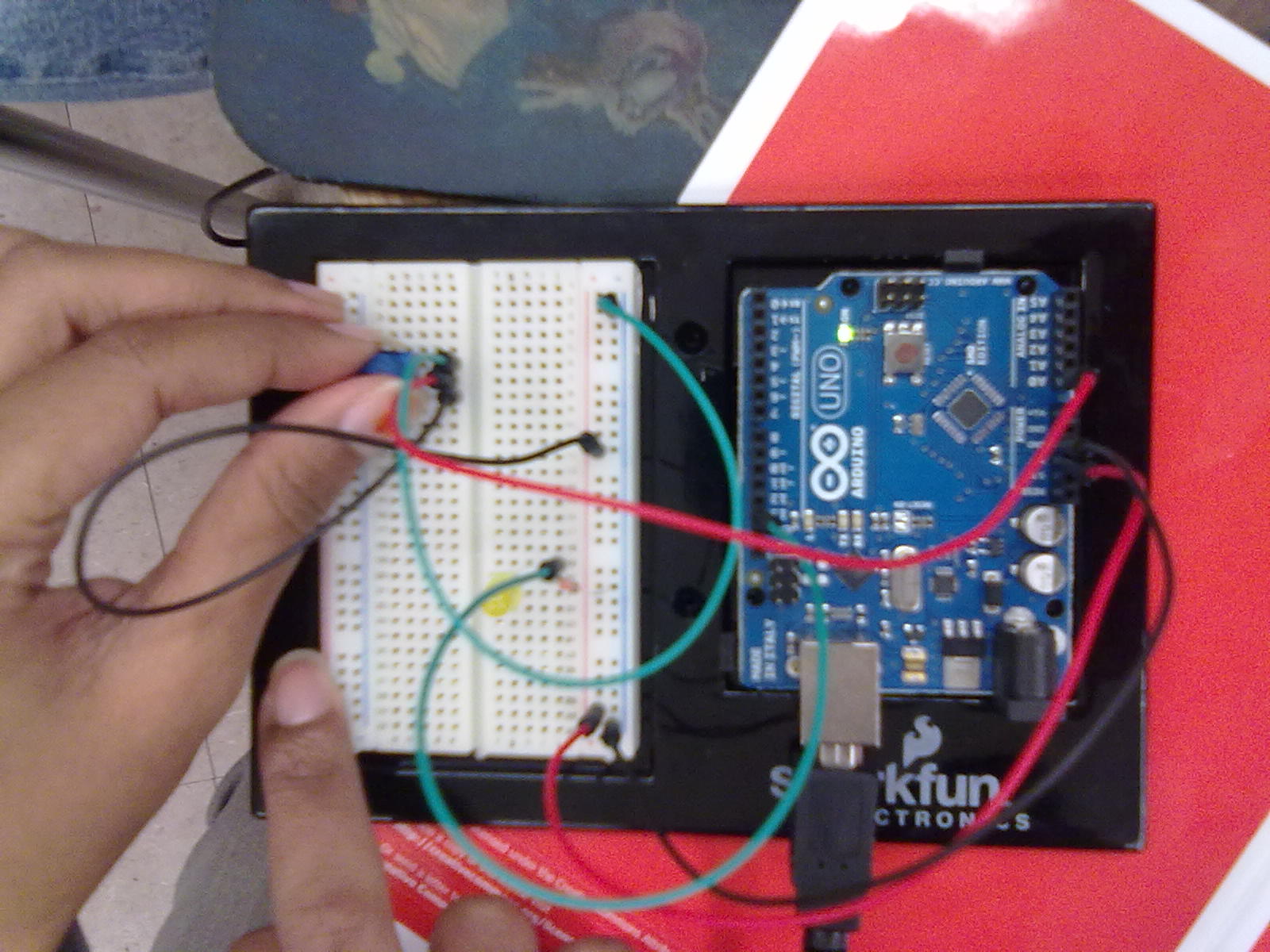


      Similar to the past lab, the program for this circuit starts by introducing the input pin (for potentiometer), output pin (LED) and a variable, in this case 'sensorValue', which receives the input values. In the loop, the program starts by reading the analog value (input) from the sensor, and storing it in the variable. The LED is then turned on, and delayed by the value of sensorValue (input value), and then turned off and subsequently delayed by the sensorValue before reading the potentiometer again. Note that the LED is actually blinking really fast (milliseconds) to produce the assigned output. The resistance corresponds to time since the analog reading translates to time in the digital reading. 


Results


     After analyzing the program and uploading it to the circuit. We played with the potentiometer, and it was nice to see the output understanding how the analog reading (sensory) translated to a digital output. This resistor seems way cooler than the small 2 pin ones. If you think about it, there are also many applications of this, such as audio control, dimming lights, television control, etc. 


Tips


     Make sure you attach the wires to the Arduino Uno without confusing the analog and digital pins, because the communication of these as input and output is integral to this circuit. Also make sure the three pins of the potentiometer are placed correctly in order for it to function. The programming, again is pretty straight forward, just make sure you know the key concept, translation of analog reading to digital, before you program the circuit.


Next Steps & Associated Program Modifications


     There are many simple modifications that can utilize the potentiometer for different purposes. This includes fading (dimming lights) and creating a switch. I think both of these are unique modifications, so below I have the code and explanations for both.


//THE SWITCH
//The assigned threshold acts as a switch


int sensorPin=0; //input pin, poteniometer
int ledPin=13;// LED pin


void setup()
{
  pinMode(ledPin,OUTPUT); //sets LED as output
}


void loop()
{
  int threshold=512; //value of the variable 'threshold', also analog
  if (analogRead(sensorPin)>threshold) //if the input from the potentiometer (sensorPin)
 // is greater than the value of threshold...
  {digitalwrite(ledPin, HIGH);} //turn the LED on
  else 
  {digitalwrite(ledPin, LOW);} //or else, when sensorPin<512, turn the LED off
  
}


/*FADING
*All of the program uses analog components. The LED is assigned the value from the *potentiometer, translated to the appropriate number of bits.
*/


int sensorPin=0; //input pin, poteniometer
int ledPin=13;// LED pin

void setup()
{
  pinMode(ledPin,OUTPUT); //sets LED as output
}


void loop()
{
  int value=analogRead (sensorPin) /4; //reads the potentiometer and divides the value by
  //4 so that it could be used by the 'analogWrite' function in the next step. This value
  //is stored in the variable 'value'
  analogWrite (ledPin, value); //the LED's state is on full power, off, or somewhere in 
  //between, depending on 'value'
  
}


Reference: Spark Fun Inventor's Guide


Pushbuttons (CIRC-07)

Purpose


To control a circuit, here specifically LEDs, using pushbuttons. Here, the user gets to control the circuit personally with touch. 


Equipment

  • 1 x red LED
  • 2 x pushbuttons
  • 1 x 220Ohm Resistor
  • 2 x 10kOhm Resistor
  • 7 x Wires
  • 1 x Breadboard & reference sheet
  • 1 x Arduino Uno 
Program Details

     This experiment is especially cool because we are controlling the circuit with our own hands, we determine the output, LED on or off. This is why the coding is simply a matter of reading our signals. Although there are two buttons attached, only one is of use right now. However, refer to 'Next Steps & Associated Program Modifications' to utilize the other button. Assembling this circuit took around 5-10 minutes. It is simply a matter of carefully following the attachments, so as to minimize any sources of error. See the assembled circuit below.

Assembled circuit

     The code for this is all straightforward. The only new concept is using a variable to read the pushbutton and control the state of the LED. First, the code declares the inputs, outputs, and variable 'val', which reads the state. The repetitive part 'loop()', the main function, uses the function 'digitalread' to read the state of the button, input. If the input value is high, unpressed, the LED is turned off. In any other time (else) the input value is low, pressed, the LED is turned on. 


Results


     First we did not notice that the second button didn't do anything, so we were worried. Soon after, we looked at the guide and realized all was good. This experiment worked as the program suggested. It wasn't as exciting as it sounded, but it was cool to learn how our own movements translate into electrical input/outputs. 


Tips


     The biggest tip would be to assemble the resistors and pushbuttons carefully, and look over the circuit before uploading the program. Since there are wires passing overhead, make sure the pushbuttons, especially close to the breadboard, is placed correctly the first time.


Next Steps & Associated Program Modifications


     Now, to utilize the second button, simply make one button turn the LED on, and the other turn the LED off. This means there will be 2 inputs. See the modified program below, as directed by the kit.


//start by introducing the pins. Order below: LED, button 1, button 2


int ledPin=13;
int inputPin1=3;
int inputPin2=2;


void setup() 
{
  pinMode(ledPin,OUTPUT); //the LED is now output
  pinMode(inputPin1, INPUT); //the first button is now input
  pinMode(inputPin2, INPUT); //the second button=input
}


void loop()
{
  if(digitalRead(inputPin1) == LOW) //if button 1 is pressed
  {
    digitalwrite (ledPin, LOW); //turn the LED off
  }
  else if (digitalRead(inputPin2)==LOW) //OR if button 2 is pressed
  {
    digitalwrite (ledPin, HIGH); //turn the LED on
  }
}


Reference: Spark Fun Inventor's Guide

Saturday, October 22, 2011

8 Outputs (CIRC-05)

Purpose

     The purpose of this investigation is to utilize the 'shit register' and create 8 outputs.

Equipment
  • 8 x Red LEDs
  • 8 x 330 Ohm Resistors
  • 1 x Shift Register
  • 19 x Wires
  • 1 x Breadboard 
  • 1 x Breadboard sheet
  • 1 x Arduino Uno
Program Details

     The breadboard sheet for this circuit is probably the most intimidating one, however it is simply a matter of strategy and patience. You must take your time. See the Tips section. This circuit utilizes wiring, LEDs and resistors from the past circuit. The shift register is simply a matter of aligning it in the right hole. After assembling our circuit and checking over the resistors numerous times, we programmed.

     The program is understandable once you understand the concept behind the shift register. This shift register recieves data of what to do from each of the 8 pins, in binary language, then outputs it to the LED. Only certain LEDs turn on, creating a blinking pattern. First the variables, and delay times are set. Then the program starts repeating the function of turning on certain lights. The number i, determines which LEDs turn on as it is sent to the 'updateLEDs()' function. The value of i, is assigned in binary to the shift register, and that determines which LED turns on. In confidence we uploaded this program and watched as only two LEDs turned on. We checked the wires and resistors, another group did as well. Until finally we realized the LEDs were the problem. We overlooked placing the LEDs in correct orientation. The +/- pins of the LED were placed into the breadboard randomly. After fixing this, our circuit worked fine. The LEDs seemed to blink in a random fashion, but after looking at the program closely, we realized the program was following a set of 255 combos in binary that is sent to the shift register. Unfortunately, there was not enough time to obtain a picture of the working circuit. However, here are pictures of the assembled, partially working circuits. 


Results

     The results are not that exciting in proportion to all the assembly, however the phenomenon behind it is quite astonishing. The one shift register provides the ability to control 8 outputs, using 255 different combinations! Note, the pattern is not random, it corresponds to the value of i, in binary, which spans 8 bits. If everything is simply wired the right way, the 8 LEDs should turn on and off as instructed.


Tips

     The ultimate advice with this circuit is to take your time, because with this many equipment, it is too easy to plug something wrong, miss something, etc. First count out the correct number of pieces. Then attach them to the breadboard one by one. For instance, all the wires, then all the LEDs, etc. The advised order is the shift register first, because it is lowest to the breadboard, then LEDs because it'd be a hassle attaching it under all that wire, then the wires. And finally the resistors, because they border everything else. Also make sure one pair of hands tends to the breadboard at a time, it is less confusing and much more efficient that way.

Next Steps & Associated Program Modifications


     Another way to control these pins is to turn them on one after another, then off one after another, similar to CIRC-02. In this code, the 'loop()', is replaced with the 'repeat function', where i counts to 8, using the 'changeLED(i,state)' function to turn the LEDs 'ON' then 'OFF'. See below.


int data=2; 
int clock=3;
int latch=4;
//the pins above are associated to the shift register


void setup()
{     //the introduced pins will be used as outputs
  pinMode (data, OUTPUT);
  pinMode (clock, OUTPUT);
  pinMode (latch, OUTPUT);
}


void loop()
{
  changeLED(int led, int state); //repeatedly run this function
}


void changeLED(int led, int state) //function which turns the LEDs on and off
{
  int delayTime=100;//delay time between each time function is repeated 
  for (int i=0; i<8; i++)//pins 0-7, so this is repeated until i is less than 8
  //which is 7
  {
    changeLED (i,1); //turns the appropriate LED on, similar to HIGH
    delay(delayTime); //delayed by 100ms before repeating
  }
  for (int i=0; i<8; i++)//for pins 0-7
  {
    changeLED (i,0); //turns the LED off, similar to LOW
    delay(delayTime); //delayed by 100ms before repeating
  }
  
}


References


1.  http://oomlout.com/a/products/ardx/circ-05/
2. Spark Fun Inventor's Guide


Monday, October 10, 2011

A Single Servo (CIRC-04)

Purpose
     To control a servo, which rotates by changing angles.

Equipment
  • 1 x 3 Pin Header
  • 1 x Mini Servo
  • 5 x Wire
  • 1 x Breadboard Sheet
  • 1 x Breadboard
  • 1 x Arduino Uno
Program Details
     
     Assembling the following circuit is not the most intimidating task. The wires are simply plugged as instructed. The 3 pin header helps to hold the servo connection in place. Complete assembly of the circuit takes about 4-8 minutes. See the assembled circuit below.


The images of above show the assembled and functional circuit.


The vocabulary used to program the servo is to some degree new, but easy. The key is to understand what controls the servo, that is position, ranging from 0 to 180 degrees. Accordingly, the program leads the servo to rotate a degree every 15 ms until it reaches 180 degrees, then rotate back to 0 degrees in the same manner. The variable 'pos' is assigned to do this. It is astonishing that a function as simple as this can be applied in something as big as an airport. 


Results


     First the connector between the servo and the 3 pin header was lose, so the servo did not pin. However after securing this connection, the servo rotated as programmed. 


Tips


     Simply make sure the connection between the pin header and servo is secure before uploading the program. Also make sure the values assigned to the variable 'pos' is within the limit (0-180).


Next Steps & Associated Program


     A slightly more complicated approach to controlling the servo would be changing the pulse directly, versus making the servo an object controlled by position. While the servo is on, it turns, for the allotted time, then it turns off, and repeats this function. See the code below.


 int servoPin = 7; //the servo is connected to pin 7, note the assembly should match this too

 void setup()
 {
   pinMode(servoPin,OUTPUT); //initialize the pin, set up purposes
 }

 void loop()//the following segment is repeated
 {
   int pulseTime=2100; //amount of time the servo will be on
   digitalWrite (servoPin, HIGH);//turn the servo on, it turns
   delayMicroseconds(pulseTime);//leave it turned on for this long
   digitalWrite (servoPin, LOW);//turn the servo off
   delay (25);//wait 25ms before repeating the segment
 }

Simply referred to the Sparkfun Inventor's Guide.

Spin Motor Spin (CIRC-03)

Purpose
The purpose of this circuit experiment is to integrate the usage of transistors and motors.

Equipment
  • 1 x Transistor P2N2222AG
  • 1 x Diode
  • 1 x 10k Ohm Resistor
  • 1 x Toy Motor
  • 7 x Wires
  • 1 x Arduino Uno
  • 1 x Breadboard
  • 1 x Breadboard Sheet
Program Details

     With the new pieces, combination of small and big ones, it is a bit of a hassle connecting them as they overlap, but it isn't hard. Again, just as the resistors are specific to the direction in which they are connected, the diode, transistor and motor is as well. This was our first problem, both our diode and transistor was wired wrong. After rewiring and programming, it worked. See the image below.

Assembled and functional motor.

     Assembly takes around 5-10 minutes. The coding corresponds directly to what happens in the circuit. The main loop consists of three segments: turning the motor on and off, setting the motor to a specific speed while on, then bringing the speed down to a specific level and turning it off, and finally, accelerating and decelerating the motor. The programming within these categories are basic, using variables such as 'delaytime' and 'onspeed' for the different numerical values in the program. To turn the motor on and off, use HIGH and LOW. For the acceleration and deceleration, the speed limits are stated then the program counts up or down, using the same format as that used for repeating a code. Note that in the 'void loop()' two segments are commented out. This means they don't run.

Results

     As mentioned earlier after rewiring certain components, and uploading the provided code, the motor worked perfectly. First we didn't realized that the motor was programmed to function in three different ways, we only noticed that it'd pause or stop working sometimes. However after analyzing the code, we understood perfectly. If you hold your finger to the motor, as shown below, you can feel the motor work.


Hold your finger to the motor to feel it work.


     Tips

     To make sure you understand whats going on with the motor, analyze the program before uploading it. This time with the assembly, attach the smaller parts, in the right direction, then attach the wires overhead. This will make it easier and faster to work on the small breadboard. Also, right after attaching a part, check to make sure it is attached in the correct direction instead of checking amidst all the other parts. 


Next Steps & Associated Program Modifications


     There are small modifications that can be made to the already existing program to make it do more than it does. This is because two segments of code with different functions are already commented out. By getting rid of the slashes, the 'void loop()' will run those segments as well. One can also change the numerical values of the variables. See the program sequence with two segments now. The code in orange is essentially not needed for this program (not copied and pasted).


int motorPin=9;


void setup()
{
  pinMode(motorPin, OUTPUT);
}


void loop() //the program runs the following segment repeatedly no matter what
{
  motorOnThenoff(); //this turns the motor on for a certain time, then off
  motorOnThenoffwithSpeed(); //turns the motor on with a particular speed, then off
  //motorAcceleration(); this segment will not run for the program
}


void motorOnThenoff()
{
  int onTime=2500; //how long the motor will be on for
  int offTime=1000; //how long the motor will be off for
  digitalwrite (motorPin, HIGH); //turns the motor on
  delay(onTime); //function above is active for the duration of 2500ms
  digitalwrite(motorPin, LOW); //turns the motof off
  delay(offtime); //function above is active for the duration of 1000ms
}


void motorOnThenoffwithSpeed()
{
  int onSpeed=2000; //what speed the motor will be when it is on
  int onTime=2500;//how long it will stay on
  int offSpeed=50;//what speed signals that the motor is off
  int offTime=1000;//how long it will be off
  analogWrite (motorPin, onSpeed);//turns the motor on to the set speed
  delay(ontime);//keeps the motor on for 2500ms
  analogWrite(motorPin,offSpeed);//turns the motor off
  delay(offtime);//keeps the motor off for 1000ms
}


void motorAcceleration();
{
  int delaytime=50;
  for (int i=0; i<256; i++);
  {
    analogWrite(motorPin,i);
    delay(delaytime);
  }
  for (int i=255; i>=0; i--);
  {
    analogWrite(motorPin, i);
    delay (delayTime);
  }
}  


Reference


The Sparkfun Inventor's Guide


Tuesday, October 4, 2011

8 Blinking LEDs (CIRC-02)

Purpose:
The purpose of this experiment is to turn multiple LEDs on and off in a sequence.


Equipment:

  • 8 x 330 Ohm Resistor
  • 8 x Yellow LED
  • 10 x Wire
  • 1 x Breadboard
  • 1 x Arduino Uno
  • 1 x Breadboard reference sheet
Program Details:

      This circuit uses techniques similar to the first circuit, but with added LEDS (8 in total). Again, assembly is straightforward, but not easy. As the amount of LEDs increases, so does the resistors, and again, keeping them in place was quite a task. See 'Tips' for advice on this part of the assembly. Assembly takes around 3-8 minutes.The image below displays the assembled circuit.

Assembled and functional circuit 2.

     The programming for this circuit uses the same basics from the first circuit, (delaytime, HIGH, LOW, etc.), but with a few new concepts such as, utilizing an array, programming the number of repeats, and using the 'oneAfterAnotherNoLoop'. The array is used in the very beginning during the setup. In this case, it simply stores all possible values for the ledpin, which the program can access. Next, the number of repetitions is set using the variable i in the function: for(int i = 0; i < 8; i++){}.After setting i to the minimum, the limit (maximum) is stated using the less than sign, and is essentially the number of repetitions. By adding 'i++' afterwards, the program is allowed to increase the value of i till it reaches the maximum. Another way to be concise in this program is using the oneAfterAnotherNoLoop, which as its name suggests, performs everything in the loop one after another repeatedly. The loop in this circuit turns each LED on consecutively, with a pause identified by the variable 'delaytime', then turns all LEDs off in the same fashion.  

Results

     After uploading the program to the circuit, a minor error surfaced. Certain LEDs did not turn on at all, while the other LEDs followed the uploaded program. First we checked the program to see if the coding for the specific dysfunctional pins were the problem, however after checking everything, the source of error turned out to be the assembly of the resistors. Here we learnt that we have to wire the resistor specifically as shown in the breadboard sheet, so that the right side of the resistor was plugged into the right component in the breadboard. After rewiring the resistors, the circuit worked fine.

The final circuit.

Tips

     With the assembly of the circuit, the only thing to keep in mind is the fragility of the resistors. Assemble the resistors last, with patience, so you get it right the first time and also stays in place. In addition to the assembly, remember to keep the programming clean. Use comments so that you can refer back to what each component of the program is if something goes wrong. If you know it well, you don't have to. 

Next Steps & Associated Program Modifications


     There are many ways to go from here. You can add more pins, or play with the the pattern in which the LEDS are turned on and off. For instance, an arduino related forum, link here,  discussed manipulating the circuit to flash each LED in ascending/descending order. The following snip-it of new program (descending flashing lights) is from the website:


void descend()
{
  int descending[] = {9,8,7,6,5,4,3,2};
  
  for (int i = 0; i < PIN_COUNT; i++)
  {
    digitalWrite(descending[i], HIGH);
    delay(100);
    digitalWrite(descending[i], LOW);
  }
}


This coding can be integrated into the program for circuit two by simply adding this code after introducing the pins and setup. See below. New coding slightly modified, integration and comments original.


int ledPins[] = {2,3,4,5,6,7,8,9}; //this introduces the connected LEDs 
//that we'll be working with


void setup() //the coding below in setup turns all the LEDs on
{
  for (int i = 0; i < PIN_COUNT; i++)
  {
    pinMode(ledPins[i], OUTPUT);
  }
}


//now add the new codes!


void descend()  //loop for the descending pattern (repeats)
{
  int descending[] = {9,8,7,6,5,4,3,2}; //the order of the LEDs that will be used
//Note that this sequence is different from the regular one

    for (int i = 0; i < PIN_COUNT; i++) //the pattern will work up till the last 
//pin. From pin 2-9. However it starts off at nothing, 0.

  {    digitalWrite(descending[i], LOW); //the program originally said HIGH, but 
//since all the LEDs are already on, they will turn off first. 

    delay(100);  //wait a tenth of a second
    digitalWrite(descending[i], HIGH); //turn the LEDs off
  }
}


Finito!!


References

  1. http://forums.adafruit.com/viewtopic.php?f=21&t=17865
  2. http://docs.google.com/viewer?a=v&q=cache:oxirS_yKWpUJ:www.sparkfun.com/tutorial/AIK/ARDX-EG-SPAR-WEB.pdf+arduno+sparkfun+starter+kit+circ-01&hl=en&gl=ca&pid=bl&srcid=ADGEEShenZ1X6WUWJcmrXmkYtGjoNz6DylD1jf6bB0E9RT7CWJOitbc2DHxsFePHchtLV3h8TXOOjgqHR7i2hU07hfYY_j9QeHqE8q5dSw3xJbhtDK7njPAydUExPLnGZFfOq4ySJasd&sig=AHIEtbS9g6laYWNOfpgAqcqz8QvV9YxUVg&pli=1


Sunday, October 2, 2011

A Blinking LED (CIRC-01)

Purpose:
The purpose of this experiment is to create a blinking effect by repeatedly turning the LED on and off.

Equipment:
  • 1 x Yellow LED
  • 1 x 330 Ohm Resistor
  • 3 x Wires
  • 1 x Breadboard
  • 1 x Arduino Uno
  • 1 x Breadboard reference sheet
Program Details:

     Since this had been the first time building this circuit, programming with C and moreover performing an arduino project, there were many new concepts. The first segment of the project, assembly, was not hard to follow as there were a minimal number of pieces and a sheet to follow up with to make the appropriate connections on the breadboard. The task was simply placing the ends of the wires or pins, in the correct hole. See the image below of the assembled circuit.

Ariel shot of the assembled circuit.
  However, this job did uncover just how delicate the wires of a resistor are. Trying to push a single resisitor into the 2 appropriate holes took a great amount of time as it kept bending. Furthermore, the pair of us learnt how to read a resistor. The first coloured band corresponded to the first digit, the second coloured band corresponded to the second digit, and the third coloured band corresponded to the number of trailing zeros. A reference table was provided in the kit, and is available on this online version.

     The programming code was directly available on the program, however we also developed an understanding for the program that was uploaded to the circuit with the aid of the comments. First the basic operation was analyzed. The 'void setup' runs once just as the power is turned on, to setup the necessary componenets for the rest of the program. Then the LED light is turned on for one second, then off for another, on for a second, then off, and so forth. Then we looked at the functions of the individual lines. The line in the 'setup' component identified the LED pin. The loop in the rest of the program turned the light by sending a 'HIGH' voltage, 'delayed' it for 1000ms then turned it of by returning it to a ground state ('LOW'). Again the pin is delayed by 1000ms so that this becomes a constant pattern.

On the whole, it takes around 4-6 minutes to build, and 5-10 minutes to program, depending on one's level of experience.

Results

     Since this is one of the simplest and most straightforward circuits in the book, we had no problems getting the LED to blink. We simply built it, made sure every part was secure, then connected and uploaded the program. It seemed like at fist it was blinking at a fast pace, but after the setup, we noted the one second delay. It was blinking perfectly until we unplugged the program. See the images below of the circuit with the LED turned on.


The LED is turned on after being programmed.
      However to ensure that the circuit functions, the most important step is to make sure that everything, most importantly the delicate resistor is completely inserted into the breadboard.

Tips

     The only hassle with this circuit would be the resistor. Treat it with extra care, and try not to bend it unecessarily. Do not apply pressure to the very top of the resistor, instead force the resistor in using the long wire on either side. In order to avoid reinserting the resistors later in the assembly, assemble the wires first, then the LED then the resistor. Working from large pieces first, to smaller ones.

Next Steps & Associated Program Modifications

     A simple next step would be changing the delay time by n, and accordingly changing the coding for the amount of time to, n x 1000. However a more advanced effect, only slightly complicated would be changing the brightness using analog components. First, the wiring has to be changed to a pin that allows analog function, such as nine. Then the coding needs to be changed. Instead of the ledpin=13, make it ledpin=9. Finally inside the loop, instead of digitalwrite (ledpin, HIGH) or LOW, type analogwrite (ledpin, b), where b is any number between 0 and 255. When b is assigned 0, the LED is off, 255 the LED is on, inbetween creates a different brightness. The time delay inbetween is optional.

int ledPin = 9; //This introduces the lead pin, which is now connected to 9
//because it has analog capabilities.

// The setup() segment below runs once when the power is turned on
 void setup()
{
// The line below makes ledpin 9 an output

pinMode(ledPin, OUTPUT);
}

// the loop() segment is repeated as long as the Arduino has power
void loop()
{
analogw
rite(ledPin, 255);
//Now the LED is on
delay(1000);
// wait for a second
analogwrite (ledPin, 5);
//the LED has a diffrent brightness
analogwrite (ledPin, 6);
//the LED is slightly brighter
analogwrite (ledPin, 7);
//the LED is even brighter
analogwrite (ledPin, 0);
//the LED is turned off

}


The link in references gives the information above. However the modified programming is not copied and pasted from this site!!


References

  1. http://docs.google.com/viewer?a=v&q=cache:oxirS_yKWpUJ:www.sparkfun.com/tutorial/AIK/ARDX-EG-SPAR-WEB.pdf+arduno+sparkfun+starter+kit+circ-01&hl=en&gl=ca&pid=bl&srcid=ADGEEShenZ1X6WUWJcmrXmkYtGjoNz6DylD1jf6bB0E9RT7CWJOitbc2DHxsFePHchtLV3h8TXOOjgqHR7i2hU07hfYY_j9QeHqE8q5dSw3xJbhtDK7njPAydUExPLnGZFfOq4ySJasd&sig=AHIEtbS9g6laYWNOfpgAqcqz8QvV9YxUVg